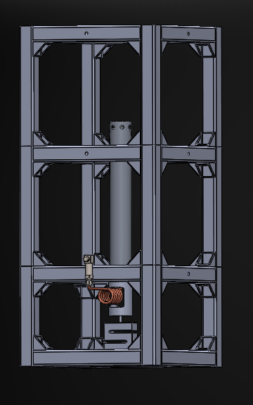
Solid Rocket Test Stand DAQ
One of HiPR’s projects this year was a solid rocket test stand, and although I didnt have much experience with DAQ beforehand, making electronics for incredibly high power motors just sounded too good to pass. Fortunately, the sensors had been specced out by the lads, and all I had to do was figure out a way to interface them with a raspberry pi we had lying around. It always fun to work on these projects, because you will almost always have to figure out how to use the components you already have at hand (as a rocketry club with several connections, you have an interesting variety).
So heres the prerequisites,
Prerequisities:
- The pressure sensor, load cell, and the thermocouples are already specced up.
- We need to use a raspberry pi, since we already have that hand.
- The sensor should be able to measure pressure data at 100Hz+, load cell at as much as possible, and thermocouples at whatever works (not that important).
- Live telemetery would be useful for safety, local logging is a must.
- A labjack U3-LV was borrowed off of some other rocketry team, plus an LJTick amplifier, making load cell much easier to work with.
- Not blowing up the stand would be prefferable.
Sensors
Pressure Transducer
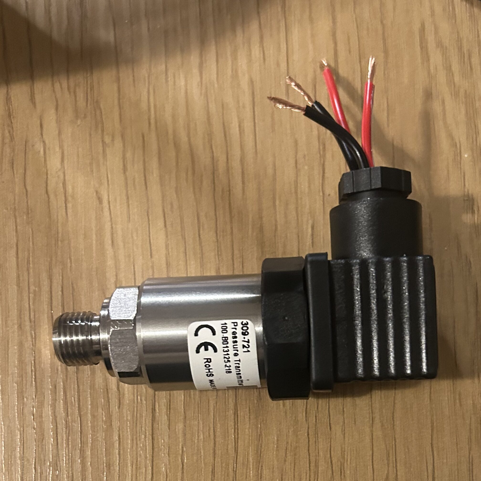
The pressure transducer we bought was the “RS PRO OPTC Series Pressure Transmitter, 0 to 10 V dc Output 0 bar 100 bar, Absolute Reading”. It needs an input voltage of more than 12-28V, so that gives a wide voltage range for the batteries. I decided to connect this to the Labjack (Basically an industrial data acquisition solution, with a really good ADC and high sample rates), since it already has a great Analog to Digital Convertor, and consolidating imortant sensors (pressure and load) is usually a good idea.
The main thing I need to do for this sensor was to step down the max 10V output to a reasonable 2.4V so that it could be measured by the Labjack. A simple voltage divider calculation gives us the necessary resistor values as follows,
Or more simply put,
The max output of the sensor is 10V, so to convert it to 2.32 (max of labjack is 2.44, and we need around 5% headroom). So thats a ratio of,
Using R2 as 10kΩ standard, we get,
Theres two problems with this setup though,
- Standard resistors with 5% or 1% errors would eat into the accuracy of the sensor. This can be solved by using lower tolerance metal foil resistors with 0.1% tolerance.
- Loading errors, although negligible are still present, and an addition of a simple op amp buffer would fix it.
- Noise of lots of different types of frequencies mess with measurement, so a low pass filter using capacitors is essential.
The final circuit looks something like this:
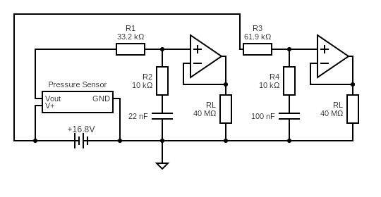
Along with the pressure sensor, I also added a battery voltage divider, so that the pi knows exactly how much battery is left. The RL resistor here signifies the resistance Labjack AIN channels give (from documentation). Now I could have used the LJTick Voltage Divider 5 for this exact thing and it would have essentially been plug and play, but spending 60 euros on a circuit I can make for 5 euros seemed a bit wasteful.
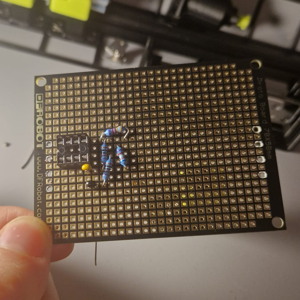
pressure divider on the protoboard
Load Cell
The S type load cell is a strain guage which, when stretched compressed, outputs a slight voltage (in the milivolts). The equation to calculate voltage output is:
Here,
Vout = output voltage
Vexcitation = input voltage (5V by the Labjack in this case)
F = force applied
F FS = maximum rated capacity
S = sensitivity
The sensitivity (S) is given by the mV/V figure, which for our load cell is 1.9899 mV/V. This means that at an excitation voltage of 2.5V (What the Labjack Provides), the max voltage output (maximum force applied) is given by,
This is too small for the Labjack to measure so we need an in-amp (instrumentation amplifier), to step up the voltage to readable levels. Theres a lot of other reasons we are using an inamp for this, but they dont need to be explained here. The LJTick handles all the complex circuitry, so we can draw up the circuit like this:
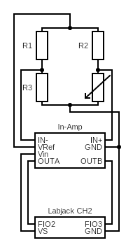
The variable resistor here represents the changing resistance of that resistor from stretching and compressing under load. The gain from the In-amp is represented by the following equation,
Voltage Reference here can either be 0.4V, or 1.25V for unipolar and bipolar signals respectively. Since we only need compression and not tension, we will use the 0.4V option. Gain is also set by the switches in the in-amp, I am selecting 261x here (We will probably be soldering a 287 ohm resistor to this so we get, a 350x gain, giving a lot more resolution), so that the after the +0.4V offset, we get a max voltage of,
The load cell will be calibrated against known weights, removing any offset errors later on, so we dont need to worry about anything else now.
Thermocouples
Probably the easiest sensors to work with, they are basically two different pieces of metals joined togethether. We are using Type-T thermocouples, so the metals in this case are constantin and copper. The working principle is that the two metals are joined at the hot junction, and when the hot junction is heated, a small potential difference (milivolts again) is generated, which is measured at a cold junction (which is at room temperature).
The adafruit max31856 breakout board takes care of the amplification, the CJC (cold junction compensation) the room temperature measurement offset, the digital conversion etc. All we need to do is connect the I2C pins from the pi to the adafruit module.
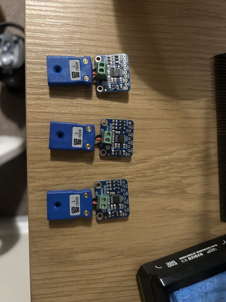
connectors to the MAX31865 module.
They need to be as close as possible
to get the most accurate cold junction compensation.
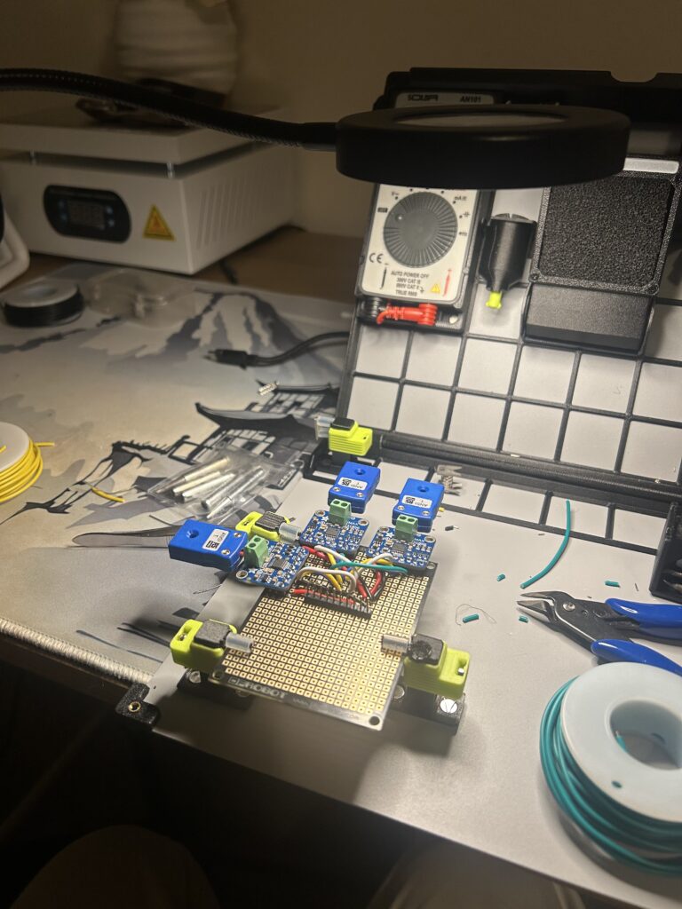
connects the sensors together in a SPI Bus
Totally worth the 3 hours it took.
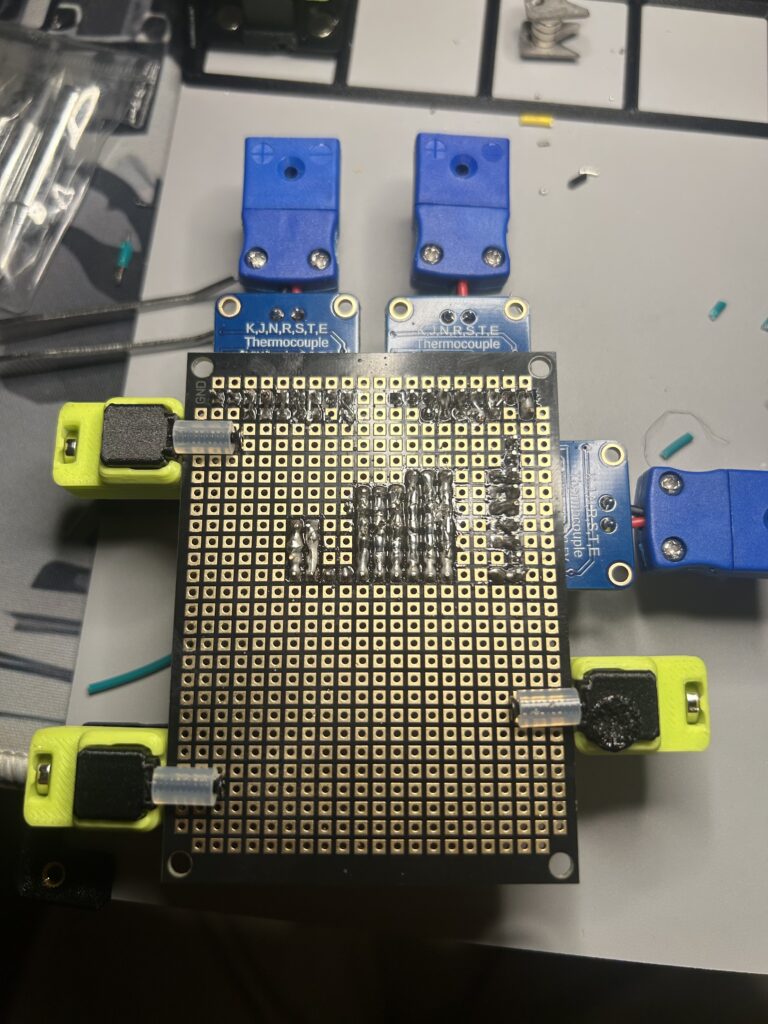
Battery
Now for the power circuitry, we just need to figure out rough estimates on how much power everything draws,
- Raspberry pi: 600 mA idle, 1.5 A max load
- Labjack U3-LV: 50 mA idle, 500 mA max load
- Adafruit max31856: negligible (few mA)
- Pressure Sensor: >8mA idle, 20 mA max load
- Load Cell: Powered By Labjack
this gives us around 2A at max load. Now everything here is powered from 5V, except the pressure sensor, which uses 12v minimum. That leaves us with very few options on the battery type. I went with a 4S Li-ion, because of high current outputs, and 14.8 volts nominal voltage (16.8 volts maximum), and ease of access. The hard part was figuring out a good way to charge this bank safely. For the BMS I went with an Ebd02 which supports 4S, and will give us over current protection, over charge protection, and a whole host of other features to make this bank as safe as possible. Unfortunately I couldnt find a BMS that did automatic cell balancing, so instead that is included in the charger which is a very simple ISDT PD60 60W Smart Charger. The cells I picked were Samsung INR18650-30Q because of their high current output at 15A (Not that we would need anything close to this, just some future proofing), and 3000 mAH capacity which is plenty for whatever we will do now or in the future. For next time, I would probably pick a BMS that already has cell balancing and maybe a higher current output (ours is 6A continous), but for now this will be more than enough.
Final Build
The final circuit is as follows,
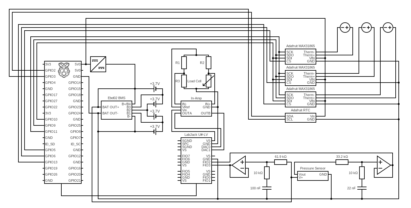
This now includes all the sensors, the voltage dividers, the breakout out boards for the thermocouples, and an RTC for accureate time keeping.